Hello everyone! First off, I need to mention that my background is in Computer Science (this project is actually for my thesis) and not in Electrical or Computer Engineering. As such, everything I've learned has been largely on my own, within the past few months.
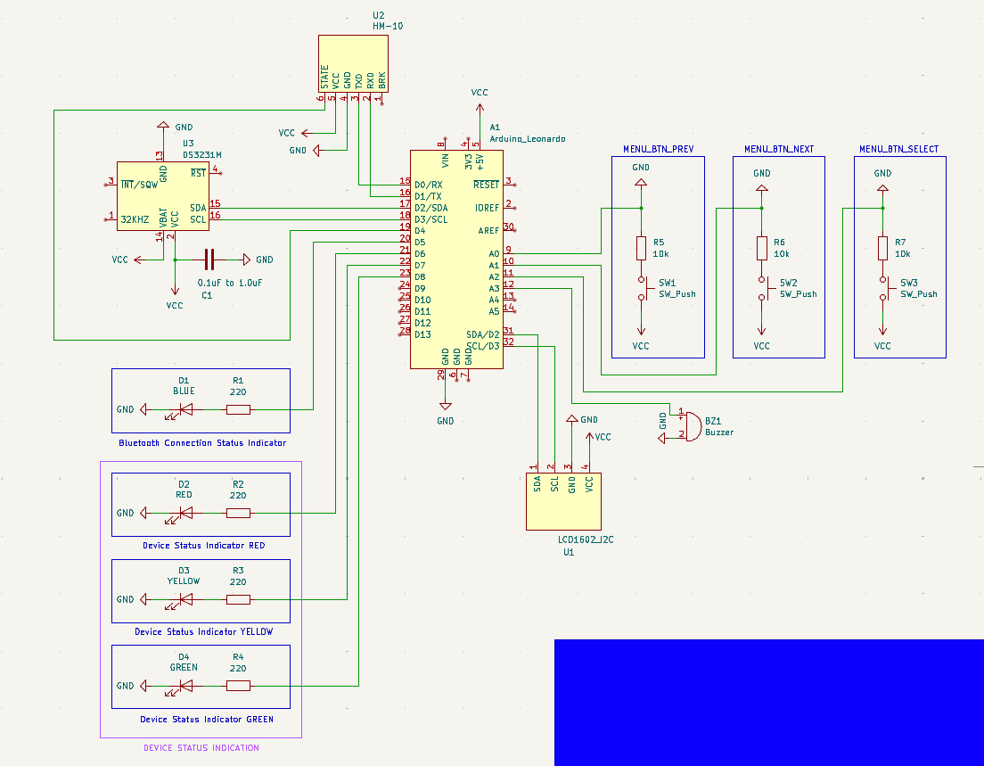
That being said, I would feel more confident if an experienced set of eyes could take a look at my schematic and let me know if anything pops out as wrong/bad practice. Furthermore, with regards to the decoupling capacitor on the DS3231M RTC module (C1 on the schematic) I have a question: Would there be any problem if I use an electrolytic capacitor instead of a ceramic one? I read some stuff about the topic and people recommend using ceramic capacitors most of the time (I think) but others say that there shouldn't be a problem to use an electrolytic capacitor. I'm asking because I've already placed an order for parts, and one of them is this assorted set of electrolytic capacitors.
Please if you notice any mistakes or things that are not done the best way let me know, and try to explain why as simply as you can. As I said, I don't have a background in EE, even though it highly interests me and I want to learn.
Here is the schematic:
Many thanks in advance!
Any electronic component (or sub-circuit) running at a high frequency can cause voltage fluctuations on the supply voltage rail. Ideally the Arduino itself has decoupling capacitors close by so those fluctuations are absorbed by those caps and never reach the RTC module. The RTC module itelf can similarily cause such fluctuations, so again, a suitable decoupling capacitor close to the component should be present. It really goes both way though. Those capacitors both reduce the influence a component has on the supply voltage, but also protects the component from fluctuations coming from the supply rail.
To better understand this, maybe it helps to consider that real circuits are never perfect. As such, PCB traces have resistance and so does the power supply. That in turn means that when the load on the power supply changes, the voltage also changes due to those resistances. With capacitors with low internal resistance near those components, those capacitors can quickly supply current when needed. This is also why you typically design PCBs with high currents with power traces in a star toplogy, so the influence between components is minimized.